Sun-Powered textiles

Fabrics with self-cleaning properties can last longer, require less maintenance and even reduce air pollution.

Sunlight can damage many types of fabrics, yet it can also have a beneficial effect on textiles that are enhanced with self-cleaning technologies. Thanks to functional coatings and pioneering research, self-cleaning properties—powered by the sun—are extending the life of textiles and decreasing maintenance costs.

Sunlight can damage many types of fabrics, yet it can also have a beneficial effect on textiles that are enhanced with self-cleaning technologies. Thanks to functional coatings and pioneering research, self-cleaning properties—powered by the sun—are extending the life of textiles and decreasing maintenance costs.

CHEMISTRY BASICS

Self-cleaning textiles are basically functionalized textiles either due to chemistry or innate biology. The hydrophilic self-cleaning coatings are based on photocatalysis: when exposed to light, they are able to break down impurities.

Two kinds of self-cleaning textiles are available. The first core technology is considered anti-stick or hydrophobic, and this type is often called antimicrobial, according to Reinhard Liu, operations manager at TitanPE Technologies Inc., a leading nano photocatalyst maker and the first hydro-synthetic photocatalyst manufacturer in Shanghai, China.

AT&T Stadium, home of the Dallas Cowboys in Arlington, Texas, features 19,000m2 of SHEERFILL® I with EverClean® Topcoat on the retractable portion of the roof. Photo: Saint-Gobain.

Liu explains that with this first type of technology, the goal is to develop textiles that do not allow pollutants to stick to the textile. “There are several chemicals that can do this in the world,” Liu says. “This technology is a dirt repellent, not ‘self-cleaning.’” The goal is to prevent dirt and microbial elements from sticking to and “dirtying” textiles and interior or exterior applications.

The second type of technology is hydrophilic and photocatalytic. “In this type of technology, we want the textile to have hydrophilic features, so we can clean it by water, even without using a cleaning agent,” Liu says. “The photocatalytic component can help decompose organics on the textile under the sun. This technology is actually self-cleaning, because we use rain and water to clean it automatically.”

TitanPE has some commercial anti-stick products, but the company’s major R&D is focused on hydrophilic and photocatalytic technology. Called TiPE™ self-cleaning nano coat, the special nano photocatalyst technology can be applied to the exterior of buildings to prevent mold, moss or dirt buildup. The coating can also improve the air around the building by purifying nitrogen oxide (NOx) generated by passing automobiles.

THE HYDROPHILICITY FEATURE

Detergents and cleaning agents reduce the surface tension of water and lower the contact angle on fabric surfaces. TitanPE Technology calls it the hydrophilicity feature. TiPE nano coat’s hydrophilicity will simulate this feature, so that a single water wash on the surface can achieve the same effect as a traditional cleaning with detergent.

The Lampton Shopping Center in Thailand features a PVC-coated fabric display coated with photocatalyst. Photo: Taiyo Kogyo Corp.

According to Liu, when the surface of nano-level photocatalytic film is exposed to light, the contact angle of the photocatalyst surface with water is reduced gradually. As explained in the TiPE nano coat self-cleaning application manual, after enough exposure to light, the surface reaches super-hydrophilicity. In other words, it does not repel water at all, so water cannot exist in the shape of a drop, but spreads flatly on the substrate. The hydrophilic nature of titanium dioxide (TiO2), coupled with gravity, will enable the dust particles to be swept away following the water stream (rain), creating the key feature of self-cleaning and easy-cleaning.

Our self-cleaning technology has been used on buildings for several years, with many clients using water/oil repellent technology first and then turning to us,” Liu says. “But for textiles, it is just a beginning. Water- and oil-repellent technology is still much higher in sales, but we are pushing it to change.”

Evidence shows the older hydrophobic treatment chemicals to be harmful to the environment, Liu notes. “We want to use a safe and long-lived technology to develop a new commercial market. It needs to be safe, healthy, environmentally friendly and also inexpensive,” he says.

The first PVC-coated fabric with TiO2 was developed by Taiyo Kogyo Corp., Osaka, Japan, in 1997. Taiyo Kogyo has been selling the products commercially since 1998. Other companies also sell hydrophobic and anti-stick products, including 3M, St. Paul, Minn., and Daikin Industries Ltd., Osaka, Japan.

Liu says, “For the hydrophilic/ photocatalytic market, it is just in the beginning.” TitanPE is a leading researcher in the area, but Liu adds that much research is happening in the U.S., which includes activity at universities and some pioneering companies.

LET THERE BE UV

“One is the oxidative decomposition reaction of organic contaminants triggered by the redox reaction of TiO2, and the other is hydrophilic property induced by UV light, whereby UV irradiation on TiO2 produces hydrophilic groups (OH groups) on the surface of TiO2 and makes the surface hydrophilic and thus gives the surface high wettability,” Toyoda says.

The hydrophilic effect allows natural rain to wash off dirt from the surface. The TiO2 top coating solution was prepared by anatase titanium dioxide crystals and is bound with an inorganic binder that largely increases the adhesion strength to the substrate.

A PVC-coated fabric with a double-layered structure.According to Dr. Hiroshi Toyoda of the Technical Research Center at Taiyo Kogyo Corp., TiO2 photocatalytic coating technology for the PVC-coated fabric shows excellent self-cleaning effects on its surface under irradiation by UV light.

According to Toyoda, because the fabric with TiO2 stays cleaner than traditional architectural fabrics, cleaning fees can be reduced and the translucency stays high, minimizing the need for further artificial lighting, which in the end will reduce energy costs for the owner.

FINDING THE RIGHT MIX

At the 2005 World Exposition in Aichi, Japan, the “Mountain of Dreams” display

featured a PVC-coated fabric with TiO2 coating. Photo: Taiyo Kogyo Corp. An example of this coating technology is Saint-Gobain’s Sheerfill® architectural membranes, which stay clean, white and bright even in very challenging environments. The fact that the fluoropolymer coating is easily rinsed clean by rain or plain water ensures a long service life with little regular maintenance, according to Michael Lussier, architectural sales and market manager at Saint-Gobain, Malvern, Pa.

“When our EverClean® Photocatalytic Topcoat was introduced to the market, our ‘easily cleaned’ coating became truly ‘self-cleaning,’” Lussier says. “By adding photocatalytic titanium dioxide to the topcoat, and simply exposing the material to sunlight—which is easy to do on a roof—a layer of activated oxygen forms at the surface, helping to reduce NOx pollution and breaking down organic contaminants. Since the TiO2 is a catalyst, it is not consumed in any of the reactions and remains available to provide the self-cleaning properties for the life of the membrane. Saint-Gobain has invested significant time, effort and money into applying the technology to our specific products.”

Lussier says that eliminating surface dirt on architectural structures is paramount, so when UV light hits the EverClean photocatalytic TiO2-based surface, hydroxy radicals (.OH) and superoxide radicals (O2-) oxidize(decompose) allorganicsubstances. Rain or water washes them away, keeping Saint-Gobain’s Sheerfill surfaces white. Maintenance cleaning is eliminated, as is the use of environmentally deleterious cleaning agents.

“The TiO2 layer is required for the PVC-coated fabric, which is used for the self-cleaning application,” Toyoda says. “It should be provided with a high photo-redox reaction ability to eliminate an oily plasticizer which migrates to the outermost surface.”

Canada Harbor Place in Vancouver, British Columbia, contains 10,000m2 of SHEERFILL® II with EverClean®. Photo: Saint-Gobain.

Saint-Gobain is one of the market leaders with respect to self-cleaning permanent architectural membranes. The company partnered with TOTO Ltd., Kitakyushu, Fukuoka Prefecture, Japan, in the development of the EverClean Photocatalytic Topcoat product; TOTO is a technical leader in the use of photocatalysts across a wide variety of products and materials.

As Lussier explains, the process of coating polytetrafluoroethylene (PTFE) onto fiberglass requires very high processing temperatures. “Finding the right TiO2 that is compatible with our materials and our processing was very challenging,” Lussier says. “It is not enough to simply add ‘TiO2’ to the coating—only the right TiO2, added in the optimum ratio, applied in the optimum manner, will provide the desired performance.”

It’s important to note that PTFE is unaffected by UV and virtually all chemicals and pollutants; the PTFE coating provides protection of the underlying fiberglass fabric, which is strong and unaffected by UV.

Adding catalytic, nano metal oxide particles to obtain self-detoxifying filter substrates is an area of focus at the Nonwovens and Advanced Materials Laboratory at Texas Tech University (TTU), Lubbock, Texas, according to Seshadri Ramkumar, Ph.D. Ramkumar is a professor at TTU’s Institute of Environment and Human Health.

“While conducting this study, we observed self-assembly phenomenon in PU nano fibers, which mimicked honeycomb structures,” Ramkumar says. “These provide more surface area and hence can be better filter substrates.”

HANDLING AND CARE

Compared to other materials that do not provide the same performance with regard to lifetime, fire safety and low maintenance needs, Sheerfill does require a different approach with fabrication and installation. Fabricators, architects, designers and owners need to understand the unique properties of the material and how to utilize it to its full potential.

The purpose of self-releasing properties of interior and exterior textiles is to minimize or completely eliminate the need for ongoing care and maintenance of these textiles and coatings. With the EverClean topcoat, cleaning will seldom be needed. When cleaning is necessary, Saint-Gobain provides simple guidelines that include using water, mild pure soap and a soft brush.

ON THE HORIZON

As Liu explains, if we look at the “real” self-cleaning aspect of textiles, from hydrophilic and photocatalytic perspectives, the current commercialization of these textiles is still on a small scale.

“We are doing some commercializing of projects for this, but it is still on a very small scale—compared to first direction hydrophobic products in the moment, but it has a big potential. After all, it will provide extra bio-pollutant control ability, which traditional self-cleaning— hydrophobic—can’t. It will allow real self-cleaning applications in hospitals, for example,” Liu says.

Continueddevelopmentsareexpanding. For instance, Saint-Gobain is developing new products to address the evolving needs of the market. These needs include the use of colors, materials with higher light transmission, mesh fabrics for shading and facades and the desire to be “green,” all while maintaining or improving the aesthetics of the final structure and providing comfort for the occupants and users.

“There is good scope for the field,” Ramkumar says. “However, one has to look into cost benefit analysis. If we are targeting consumer textiles, cost also plays an important role. End users get a value-added product. Fabricators develop new lines of value added and high performance products. But, that said, the industry has to be always cognizant of the cost factor.”

Liu predicts strong interest in further commercializing the application for building textiles, air purification and water treatment to remove harmful chemicals.

“There will be increased growth in self-cleaning textiles for use in hospitals to help control bacteria, super bugs, mutant viruses without using heavy metal,” Liu says. “There will also be further development in textiles for strong active smell control ability—to remove smoke, human body smell, sweat smell.”

Future focus will be on biomimicry, wearables and sustainable products, according to Ramkumar. He notes that the advanced fabrics industry needs “to look outside the box and borrow ideas happening in non-textile and allied fields.” For example, developing porous textiles using the supercritical fluid concept.

“While current products focus on the photocatalysis triggered by UV light, we are developing novel photocatalysis that can be triggered by visible and infrared light,” Toyoda says. “This may provide further benefits to the current technology in order to find new applications.”

The terms used within the self-cleaning textile industry are numerous. Some of the key terms to know include:

  • Bioactive textile:
    Contains an active substance with a permanently antimicrobial effect.

  • Photocatalysis: 
    The acceleration of a photoreaction in the presence of a catalyst. In catalyzed photolysis, light is absorbed by an adsorbed substrate.

  • Nanotextiles:
    Textiles engineered with small particles that give ordinary materials advantageous properties.

  • ETFE coated:
    Ethylene tetrafluoroethylene (ETFE) is a fluorocarbon-based polymer designed to have high corrosion resistance and strength over a wide temperature range.

  • Lotus effect:
    Self-cleaning properties that are a result of ultra-hydrophobicity; dirt particles are picked up by water droplets due to the micro- and nanoscopic architecture on the surface, which minimizes the droplet’s adhesion to that surface.

Assembly One Pavilion / Yale School of Architecture Students

© Chris Morgan Photography’
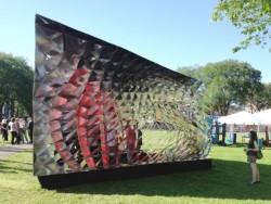
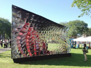
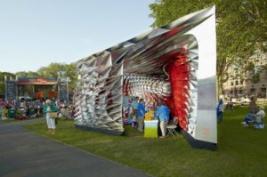
The Yale ‘Assembly One’ pavilion is the younger, smaller, more carefree sister to Yale’s building project – a 40-year old tradition in which first-year students design and building a house. It is the product of a seminar and design studio in which students focused on alternative ways in which contemporary buildings can come together and the potential architectural effects computational and material techniques can offer. The ‘Assembly One’ pavilion is designed to act as an information center for New Haven’s summer International Festival of Arts and Ideas and therefore was developed with the following characteristics in mind: dynamism, visual transparency and visual density.
   
© Chris Morgan Photography


Dynamism: The structure is suited to a performance festival – solid and massive from one angle, lightweight and almost entirely porous from another, it alternately hides and reveals its contents.
Visual Transparency: Constructed from thin  sheets, the pavilion opens up on two sides for ventilation and security, focusing views toward the festival’s main stage.
Visual Density: Over 1000 panels create shifting effects of reflection and color as visitors move around the pavilion, creating less of a timeless image of shelter than an unstable, engaging heart of the festival.


“We treated the tenets of digital fabrication as basic assumptions – our ability to efficiently produce variable and unique components and the cultural implications of moving beyond standardized manufacturing. But, we were less concerned with the uniqueness of the objects we created than on the novel types of tectonic expression they allowed.”The Festival Pavilion was designed and built by  students.

Project Founders: David Bench, Zac Heaps, Jacqueline Ho, Eric Zahn
Project Managers: Jacqueline Ho, Amy Mielke
Design & Fabrication: John Taylor Bachman, Nicholas Hunt, Seema Kairam, John Lacy, Veer Nanavatty
Design: Rob Bundy, Raven Hardison, Matt Hettler
Faculty advisor: Brennan Buck
Assistant: Teoman Ayas
Consultant: Matthew Clark of Arup, New York

Generous support was provided by Assa Abloy, the Yale Graduate and Professional Student Senate, and the Yale School of Architecture. The Pavilion is on view on the New Haven Green until the end of June.
© Chris Morgan Photography

Catalan Free-form Vault design from ETH Zurich

A stunning Catalan free-form vault has been designed and build by students during a one week workshop organised by Prof. Deplazes and Prof. Block from ETH Zurich. RhinoVAULT has been used for the design of the complex compression-only shape. For details, visit the homepage of the BLOCK Research Group.

Flow Over a Double-Sided Membrane

Submitted by symscape on September 17, 2012 – 14:04


Symscape, Computational Fluid Dynamics for All has been working with our team to find a optimum workflow for wind fluid flow on tensile surfaces. After months of work we have made available a connection between ixForten 4000  and Caedium Professional platform.


ixForten 4000  models can be easily  exported to Caedium  for wind flow analysis  and after running the simulations, Cp values and P values are reimported into ixForten 4000  for non-linear structural analysis.

This connection between ixForten 4000  & Caedium opens a wide range of new possibilities in the design of membrane and tensile structures making the Platform ixForten 4000 Premium + Caedium  the most valuable tool for workflow.

Tutorial for flow over a doubly curved surface

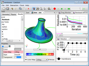
To simulate an incompressible, steady-state, turbulent flow over a double-sided membrane. View velocity vectors, velocity magnitude color maps, monitor lift and drag forces, and export results for ixForten 4000.

Caedium Membrane CFD Simulation

Caedium Membrane CFD Simulation

Goals

In this tutorial, you will learn how to:
  • Specify fluid conditions on a single volume for an incompressible, steady-state, turbulent flow simulation
  • Specify boundary conditions on faces
  • Specify meshing parameters
  • Generate a velocity magnitude color map
  • Generate velocity vectors
  • Create lift and drag force monitors
  • Monitor residuals to determine flow simulation convergence
  • Export results for ixForten 4000

Assumptions

  1. You have activated the Caedium RANS Flow and Viz Export add-ons, or Caedium Professional.
  2. You are familiar with Caedium essentials.
  3. You have either:
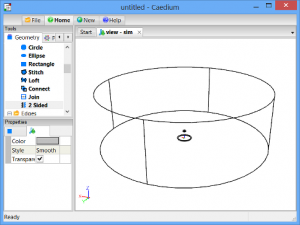
The geometry within Caedium should appear as shown below.
Double-Sided Membrane

Prepare the Volume

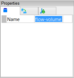
Right-click an edge of the volume, double-click the first volume (volume_2) in the Select dialog and then select Properties from the menu. In the Properties Panel, select the Volume tab  and set theName to flow-volume.
Volume Name Property

Create Membrane Group

Create a group for the membrane and its shadow so that later on in this tutorial you can monitor the integrated drag and lift forces.
Right click on the membrane base edge. In the Select dialog selectface_6-shadow, press the Ctrl key and select face_6 in the Selectdialog, click OK, select Group, and then select Properties.
In the Properties Panel, select the Group tab  and set Name tomembrane.
Specify the Substance Settings

Specify the Fluid Conditions

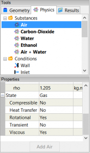
Select the Physics Tool Palette. Select Substances->Air. The Properties Panel will show the default properties for air. To enable incompressible turbulent (viscous) flow the State->Rotational and State->Viscousproperties should be set to Yes (their default values), and the State->CompressibleState->Heat Transfer and State->Transient properties should to be set to No (their default values).
Air Properties
Drag and drop the Substances->Air tool onto an edge of the volume. Select Done to set air as the fluid inside the volume.

Set the Reference Velocity for the Simulation

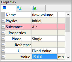
The reference velocity will be used to initialize the simulation and to specify the free stream velocity boundary condition. In this tutorial you will set a reference velocity of [8.66 5 0] m.s-1, from 10 m.s-1 @ theta = 30 degrees to give [10 * cos(30), 10 * sin(30), 0].
In the Properties Panel set Substance: Air->Properties->Phase: Single->Reference->U: Fixed Value->Value to be [8.66 5 0] and press Enter on the keyboard.
Reference Velocity Property

Set the Non-Orthogonal Corrections for the Simulation

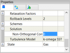
In the Properties Panel, expand the Substance: Air->Solver: RANS Flow->Solution property, and then set Non-Orthogonal Corrections to be 0.
Non-Orthogonal Corrections Property

Specify the Boundary Conditions

Wall Conditions

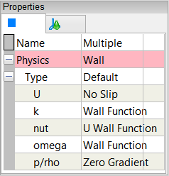
Drag and drop the Conditions->Wall tool onto an edge of the volume. Double-click flow-volume->Faces in the Select dialog and select Doneto create walls on the outer surfaces of the volume.
A Wall condition is a solid surface through which fluid cannot flow.
Wall Properties

Inlet-Outlet Conditions

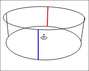
Drag and drop the Conditions->Inlet-Outlet tool onto edge_8 (blue). In the Select dialog select face_1, press Ctrl and select face_5 in theSelect dialog, click OK, and select Select/Deselect. Select edge_7 (red) in the View Window, in the Select Dialog select face, press Ctrl and select face_4, click OK, select Group, and select Done.
Inlet-Outlet Edges
In the Properties Panel, set Name to be circumference, and set Physics: Inlet-Outlet->Type to be Free Stream.
An Inlet-Outlet condition of type Free Stream allows the fluid to enter or leave the flow domain.
Free Stream Properties

Slip Condition

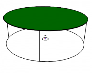
Drag and drop the Conditions->Slip tool onto an edge of the face shown in green below, double-click face_3 in the Select dialog and select Done.
Slip Face
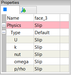
A Slip condition ensures the flow velocity remains tangential to a face.
Slip Properties

Specify Meshing Parameters

You do not need to apply any volume or boundary condition prior to focusing on the meshing process – all that is required is an active Substance on your flow domain.

Face Mesh

First you will focus on the surface mesh to avoid the extra time required to create the volume mesh.
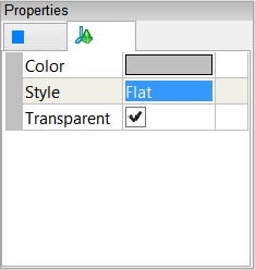
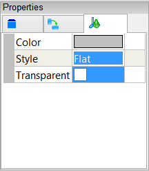
To see individual surface mesh elements during the meshing process, right-click on the View Window background, double-click sim->Faces, and select Properties from the menu. In the Properties Panel, set Style toFlat.
Faces Style Property
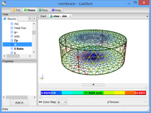
Select the Results Tool Palette. With all faces still selected from the previous operation select the Scalar Fields->A (area) tool, click Add A at the bottom of the Properties Panel and select Color Map.
The request for the A color map will cause all the faces to be meshed.
Face Mesh
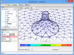
Zoom the view using the mouse wheel to focus on the membrane mesh.
Membrane Face Mesh
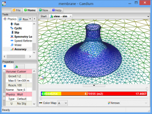
Select the Physics Tool Palette and select the Conditions->Accuracytool. In the Properties Panel set Accuracy to Custom and set Resolutionto 100. Drag and drop the Conditions->Accuracy tool onto a membrane edge, double-click face_6 in the Select dialog, and select Done.
Applying the Accuracy tool will cause all the faces to be remeshed which will take a few seconds.
Fine Membrane Face Mesh

Volume Mesh

To see individual volume mesh elements during the meshing process, right-click on any edge in the View Window, double-click flow-volume, and select Properties from the menu. In the Properties Panel, turn off theTransparent property and set Style to Flat.
Volume Style Properties
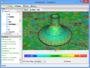
Select the Results Tool Palette. With the volume still selected from the previous operation double-click the Scalar Fields->Vol Ratio (volume ratio = actual volume/ideal volume) and select Color Map.
The request for the Vol Ratio color map will cause the entire volume to be meshed which will take a few seconds.
Volume Mesh
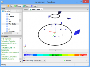
Drag the upper threshold slider to the left in the View Legend to examine the cells with the lowest quality (lowest value in the blue range).
Volume Mesh Threshold
If you were to see clusters of low quality cells attached to the geometry then that is a sign that you need to improve the mesh in that region using the Accuracy tool. Fortunately this mesh does not suffer from low quality element clusters and you can proceed on with the simulation.

Display Initial Velocity Color Map

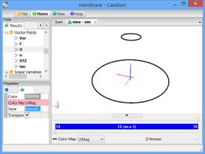
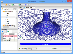
Drag and drop the Vector Fields->U (velocity) tool onto the View Window (view) background, double-click sim->Faces, select Color Map to create contours of velocity magnitude on all faces.
Velocity Color Map
In the Properties Panel, set Style to Smooth.
Smooth Velocity Color Map
Check that the velocity magnitude value (shown in the View Legend color bar) matches the value you expect as confirmation that your reference velocity is correct.

Display Initial Velocity Vectors

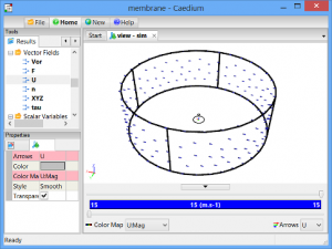
Drag and drop the Vector Fields->U (velocity) tool onto an edge of the circumference faces, double-click the circumference group in the Selectdialog, and select Arrows to create arrows colored by velocity magnitude.
Arrows
Check that the arrows are oriented in the direction you expect as confirmation that your reference velocity is correct.

Create New Drag Result

Given that the air direction for this simulation can vary, i.e., it is not aligned with the X-axis, you need to create a new result for the drag force = Sum(F:X.Cos(theta) + F:Y.Sin(theta)), where F is force per element and theta is the angle between the air direction and the X-axis in the XY-plane.
The steps to calculate the new drag result are:
  1. Create a scalar constant theta
  2. Create Cos(theta) and Sin(theta)
  3. Create F:X.Cos(theta) and F:Y.Sin(theta)
  4. Create F:X.Cos(theta) + F:Y.Sin(theta)
  5. Create Sum(F:X.Cos(theta) + F:Y.Sin(theta))

Create Scalar Constant theta

In the Toolbar, click the New button  and select Result.
In the Create Result dialog, select the Constant tab. For Units, selectAngle.
Click Create to create a scalar.
In the Results Tool Palette, select Scalar Variables->Scalar (the scalar variable you just created), click on it again to make its name editable, and change Scalar to theta.
In the Properties Panel, set the Value of theta to 30. Press Enter on the keyboard to apply the changes to the Properties Panel.

Create Sin(theta) and Cos(theta)

In the Create Result dialog, select the Unary tab. Select Sin from the list. Drag Scalar Variables->theta from the Results Tool Palette and drop it onto the target in the Create Result dialog and click Create to createSin(theta).
Perform the same procedure again but select Cos from the Unary operators list to create Cos(theta).

Create F:X.Cos(theta) and F:Y.Sin(theta)

In the Create Result dialog, select the Binary tab. Select Multiply from the list.
In the Results Tool Palette, select Vector Fields->F (force). In the Properties Panel set Scalar to X.
Drag and drop Vector Fields->F onto the left-hand target in the Create Result dialog. Select Scalar to specify the X-force-component as the left-hand variable for the equation.
Drag Scalar Variables->Cos(theta) from the Results Tool Palette and drop it onto the right-hand target in the Create Result dialog and clickCreate to create (F:X x Cos(theta)).
In the Results Tool Palette, select Vector Fields->F (force). In the Properties Panel set Scalar to Y.
Drag and drop Vector Fields->F onto the left-hand target in the Create Result dialog. Select Scalar to specify the Y-force-component as the left-hand variable for the equation.
Drag Scalar Variables->Sin(theta) from the Results Tool Palette and drop it onto the right-hand target in the Create Result dialog and clickCreate to create (F:Y x Sin(theta)).

Create F:X.Cos(theta) + F:Y.Sin(theta)

In the Create Result dialog, select the Binary tab. Select Add from the list.
Drag and drop Scalar Fields->(F:X x Cos(theta)) onto the left-hand target in the Create Result dialog. Drag and drop Scalar Fields->(F:Y x Sin(theta)) onto the right-hand target in the Create Result dialog and clickCreate to create ((F:X x Cos(theta)) + (F:Y x Sin(theta))).

Create Sum(F:X.Cos(theta) + F:Y.Sin(theta))

In the Create Result dialog, select the Unary tab. Select Sum from the list. Drag Scalar Fields->((F:X x Cos(theta)) + (F:Y x Sin(theta))) from the Results Tool Palette and drop it onto the target in the Create Resultdialog and click Create to create Sum(((F:X x Cos(theta)) + (F:Y x Sin(theta)))).
Close the Create Result dialog. In the Results Tool Palette, select Scalar Variables->Sum(((F:X x Cos(theta)) + (F:Y x Sin(theta)))) and rename itDrag.

Create Force Monitors

Drag Monitor

Drag and drop the Scalar Variables->Drag tool onto a membrane edge. Double-click the membrane group in the Select dialog and selectMonitor.
Drag and drop the Drag Monitor tab over to the right-hand edge of the Caedium application window to split the window into two parts as shown below.

Lift Monitor

In the Results Tool Palette, select Vector Variables->F (force). In the Properties Panel set Scalar to Z.
With the membrane group still selected from the previous Drag monitor creation, double-click the Vector Variables->F tool and select Monitor.
Drag and drop the F Monitor tab over to the right-hand edge of the Caedium application window to split the window into three parts as shown below.

Create Residuals Monitor

Left-click in the View Window to give it focus. Drag and drop the Special->Residuals tool onto a membrane edge. Double-click flow-volume in theSelect dialog and select Monitor to create the residuals monitor.
Drag and drop the Residuals Monitor tab over to the top-right-hand edge of the Caedium application window to add the monitor to the drag monitor tab row as shown below.
Residuals Monitor

Run the Flow Solver

The number of flow (simulation) solver iterations is determined by multiplying the number of simulation time-steps (default = 5) by the number of iterations per simulation time-step (default = 100). The number of simulation time-steps is determined by dividing the simulation duration (default = 5 s) by the simulation time-step (default = 1 s). After each simulation time-step (equivalent to 100 iterations by default) the results will be refreshed. For this simulation the defaults are fine and will result in a total of 500 iterations.
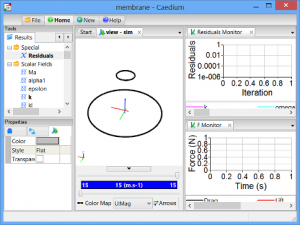
To run the flow solver, click Play  on the Toolbar.
If you wanted to interrupt the flow solver, you would re-click the Play button; the solver would then stop at the end of the current simulation time-step.
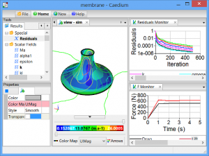
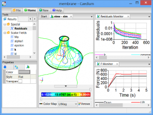
Let the solver complete its run. Note the updates of the velocity vectors, velocity color map, the forces monitors, and the residuals monitor as the simulation progresses.
Solved
Solver convergence is indicated by:
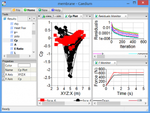
  • The Residuals Monitor shows the solver residuals decreased with increasing iterations smoothly and progressed below 0.001, i.e., over 3 orders of magnitude reduction
  • The Drag and F monitors both show convergence close to single values with increasing iterations
To make it easier to differentiate between the inner and outer membrane results, select the membrane base edge, in the Select dialog double-clickface_6 (inner results), and select Properties. In the Properties Panel, turn off the Transparent property.
Shaded Inner Membrane Face
If you change the reference velocity flow direction then you will also need to change theta used by the drag monitor. Select the View Window background, in the Select dialog double-click sim. In the Properties Panel select the Simulation tab  and set Constants->theta accordingly.
Export Results to ixForten 4000

ixForten 4000 can import CFD results from Caedium as Alias/Wavefront (.obj) for the geometry and as Comma Separated Values (CSV) for the Pressure Coefficient (Cp) data.

Create New View

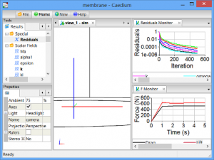
Click the New button on the toolbar and select View to create view_1.
New View

Export the Membrane as .obj

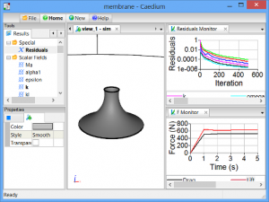
Select the membrane base edge, in the Select dialog double-click face_6, and select Properties. In the Properties Panel turn off the Transparentproperty.
Shaded Membrane
Right click on the View Window (view_1) background, in the Select dialog select sim->Edges, press the Ctrl key and select sim->Axes in theSelect dialog, and click OK. In the Properties Panel turn on theTransparent property.
This should leave only the membrane face visible ready for export.
In the Menu Bar, select File->Export…. In the Export dialog set Save as type to Alias/Wavefront (*.obj), set the File name to membrane-cp.obj, and click Save.
In addition to the membrane-cp.obj file the export operation will also save a membrane-cp.mtl file.

Export Cp Data as .csv

Drag and drop the Scalar Fields->Cp (pressure coefficient) tool onto the shaded membrane face in view_1. In the Select dialog double-click themembrane group, and select XY Plot to create a plot of the Cp values on the membrane faces.
Cp Plot
Select File->Export…. In the Export dialog set Save as type to Plot Series (*.csv), set the File name to membrane-cp.csv, and click Save.

Caedium v4 Sneak Peek: Tensile Membrane Structure Analysis

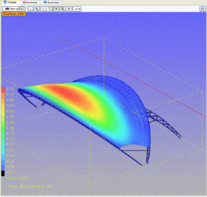
Membrane Displacement Calculated by ixForten 4000

Model: courtesy of SobreSaliente Ltda, 
Cp data source: Caedium Professional

By the time this is out, the next version of Caedium will be able to perform a CFD simulation of a tensile membrane structure and then export surface pressure coefficient (Cp) data for structural analysis in ixForten 4000. This exciting development will allow ixForten 4000 users to perform non-linear stress analysis to better determine membrane displacement with more precise wind pressure loads than previously available, leading to more cost efficient structures and supports.


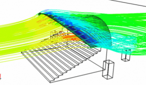
As an example of the new capability, Gerry, first exported the original membrane, from ixForten 4000 using the Wavefront file format (.obj). Next Gerry imported the Wavefront geometry into Caedium, configured the flow volume and physics, and then ran the CFD simulation.
Caedium v4 Membrane CFD Simulation: Streamlines

Caedium v4 Membrane CFD Simulation: Streamlines

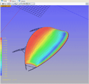
Caedium v4 Membrane CFD Simulation: Surface Pressure Coefficient (Cp)

Caedium v4 Membrane CFD Simulation: Surface Pressure Coefficient (Cp)

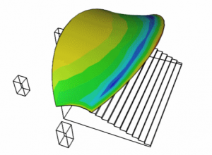
Next Gerry exported the Cp surface data and corresponding surface mesh from Caedium for import back into ixForten 4000.

Membrane Cp Displayed in ixForten 4000

Membrane Cp Displayed in ixForten 4000


As the final stage of the process, Gerry ran a non-linear structural analysis in ixForten 4000 using the Cp data as the boundary loads for the membrane. The results from the ixForten 4000 simulation are shown as displacement contours in the image at the top of this post.

The results have been quite encouraging and Now, the CFD module has slowly been integrated in the gold version of the software.

Adaptive Construction: A timber tensile roof that adapts to loads


Structures have always been designed for an exact maximum stress; this type of stress, however, generally only occurs very rarely and then only for a short period. As a result a large part of the building materials used today therefore serves these extremely seldom peak loads and is effectively seldom used. 

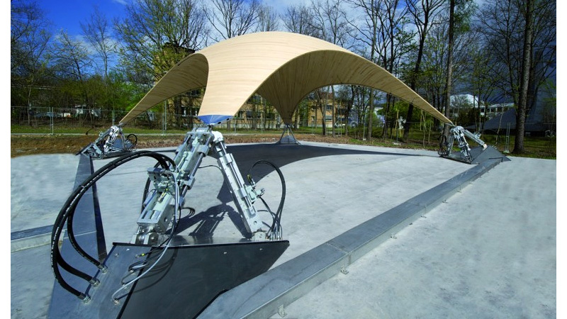
The aim of ultra lightweight structures developed at the University of Stuttgart is therefore to achieve a drastic saving of materials and a better reaction to dynamic loads through an active manipulation of the structure. In the case of the Stuttgart wooden shell this manipulation is achieved through hydraulic drives: these drives rest on the points of support of the shell and generate movements that compensate in a specific way for deformations and material stresses caused by wind, snow and other loads.

Institute for Lightweight Structures and Conceptual Design (ILEK) and Institute for System Dynamics (ISYS) of the University of Stuttgart in cooperation with Bosch Rexroth have realised an adaptive structure on a large scale for the first time. The shell made of wood is supported at four points. Three of these points can be moved individually by hydraulic cylinders and freely positioned in space. Sensors record the load status at numerous points on the structure. Targeted movements of the points of support counteract variable loads (for example through snow or wind) and thus reduce deformations and material stresses. Compared to conventional, passive structures this considerably reduces the use of materials for the shell. The load balancing takes place through a Rexroth control system which was especially developed for hydraulic drives. The core task of the control system is to implement the complex hydraulic control tasks of the shell structure. In this way the supporting structure can react to a change in the load status within milliseconds.

An active vibration dampening and the adaptation to changing loads can be applied in many areas of construction, for example in stadium roofs, in high-rise buildings, in wide-spanning façade constructions or in bridges. The results of the research project at the University of Stuttgart thus enable a completely new construction method which not only saves resources but at the same time also considerably increases the performance of supporting structures. The active dampening of dynamic loads (for example from the effects of wind, earthquake or explosions) namely enables not only a drastic reduction in weight but furthermore also reduces material fatigue and damage to the structure.

In order to be able to actively compensate loads and vibrations, these influencing factors initially have to be precisely recorded resp. predicted; a second step would be to calculate the necessary counter-movements in real time (and likewise promptly to implement them). Researchers from the University of Stuttgart developed simulation models for this purpose, enabling an exact prediction of the behaviour of the structure. The material stress as well as the vibration behaviour under static and dynamic exposure is thereby taken into account. These simulation models serve as a basis for the development of control concepts which calculate the necessary counter movements on load and vibration compensation depending on the recorded measured values. These movements are then precisely implemented through the hydraulics.

Read more about it Here and Here


Project participants: 
Institute for Lightweight Structures and Conceptual Design (ILEK), University of Stuttgart 
Prof. Werner Sobek, Stefan Neuhäuser, Christoph Witte, Dr. Walter Haase

Institute for System Dynamics (ISYS), University of Stuttgart 
Prof. Oliver Sawodny, Martin Weickgenannt, Dr. Eckhard Arnold
Bosch Rexroth AG, Lohr a. Main 
Dr. Johannes Grobe, André Fella

Contacts: 
Stefan Neuhäuser: Tel.: 0711 685-63705, 
Martin Weickgenannt: Tel.: 0711 685-66960,
André Fella: Tel.: 09352 18-1010, 

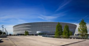
Stadion Miejski Wroc?aw

Architects: JSK Architekci 

Location: Wroc?aw, Poland
Architect In Charge: JSK Architekci 
Design Team: Zbigniew Pszczulny, Mariusz Rutz, Piotr Bury (project manager)
Project Year: 2011
Photographs: JSK Architekci

Project Area: 248,401 sqm
Landscape Architect: RS Architektura Krajobrazu
Structure: Schlaich Bergermann und Partner (steel structure), Matejko i Partnerzy Biuro Konstrukcyjne (RC structure)

Background
UEFA’s decision to select Poland and Ukraine as the hosts of EURO 2012 encouraged the city of Warsaw to organize an architectural competition for the new stadium which would hold 40 thousand seats and be prepared to host group matches of EURO 2012.  21 renowned architectural practices were invited to compete. Polish practice JSK Architekci was awarded with the first prize and in October 2007 the office was granted the commission to deliver the project.

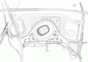
Development site is 7km outside of Wroclaw city centre. Existing infrastructure surrounding the new stadium was improved by the new motorway bypass and the new tram line providing additional access to the site from west and north. Stadium development had a positive impact on the economical growth of the surrounding neighbourhood with plans of further development i.e. a new office park and the first in Poland shopping mall strictly adjacent to the stadium.

Concept design
The stadium building and its surrounding were designed to present both interesting architectural form and fulfil requirements of economical exploitation yet providing maximum functionality and flexibility. The design of the site plan emphasizes the main building of the stadium making it a dominant feature in the surrounding space. Platform surrounding the stadium on the entrance level (6m above the ground) descends gently (4% fall) to the ground level under the street overpass allowing a comfortable and collision free pedestrian connection to the railway and tram station to the south, also covering level 0 of the stadium plot with VIP entrance, driveway and parking places. Separating main stream of pedestrians from the remaining vehicular circulation routes created a friendly and welcoming entrance zone to the building.


This plateau provides the pedestrians with an extensive space and a roof for the parking lot and the service road. The plateau from the north western side is woven by with the rising plateau of the car park. This rising roof level of the car park hides the one for a shopping centre tied area. Conceived as a single tiered stadium with a uniform stand bowl, makes it possible for the spectators to be aware of a sporting event in a more exciting way. Despite the great building scale it has been successful to keep an intimate atmosphere on the whole stand. So we can experience a unique atmosphere. This stadium in its scale is one of the few with a single tier.


A clear and apparent scheme of the functional design makes a fluent admission into the stadium building possible. The bowl of the semicircular stand is attainable from 2 promenades on 2 levels. Numerous turnstiles which allows us to run onto the lower promenade are placed in a complete radius of the building. The upper promenade is easily attainable with the help of open stairwells. Both promenades form a kind and comfortable space with all possible welfare facilities (catering trade, toilets, first help, police). For a luxury the promenades were wrapped by a transparent membrane. On the one hand it offers protection of bad weather conditions, on the other hand it is closing the building form visually. The number of pillars was reduced considerably so that spacious and open promenades could be created.

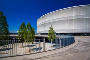
Building rentable area organizing system is quite unique. Conventional designs usually locate rentable areas underneath tribune structures, Wroclaw’s stadium separates them from the structure by creating a promenade and a massive void allowing visitors admiring tribunes from underneath. Along promenades toilets and retail units ready to service 40 thousand visitors were located. Open staircases leading spectators up to the top level strengthen the feeling of openness and allow for the exposed reinforced concrete structure to be admired. Standing out mesh membrane is characteristic for the new Wroclaw stadium. It consists of a polytetrafluoroethylene covered fibreglass and is pushed on 5 ring beams of steel. The 5 ring beams refer by the horizontal geometry to the well-known Wroclaw’s modern architecture.


Stadium design was based on UEFA and FIFA guidelines supplemented with the experience of EURO 2006. All the tribune seats are roofed and provide unobstructed view of the pitch. Both promenade levels are duly serviced. On its western side business club and VIP hall were located.  Zone for footballers and media has been envisaged as well. Level +3 holds lodges with the conference rooms featuring rows of seats facing the stadium arena. Stadium will also be home to sport bar, offices, physiotherapy centre, fitness club, discotheque, casino etc. Diversification of available services allows the building to be used all day long.


Structure
The main bulk of the stadium building consists of three main elements:
– Tribunes construction of reinforced concrete.
– Steel construction of the roofing structure, with its oval shape repeated in the form of three rings at varying angles surrounding the building.
PTFE covered fibreglass mesh membrane stretched on the above mentioned steel rings.


Roof design is formed with the light cantilevered steel structure consisting of 38 radially spread trusses sitting on a pair of columns each (one is pressured the other tensioned). The stadium roof generally appears as membrane roof with a glass ring part designed to bring maximum amount of sunlight to the pitch.


Facade
Facade belting the stadium starts at the height of 3.5m above esplanade level.  Its structure consists of 5 steel beams – rings and it is covered with partially transparent mesh membrane. Façade’s form results from the shape and arrangement of the steel rings formed with curved steel pipes. The lowest and the highest rings are placed horizontally keeping distance of 30m between them. This dimension determines the height of the mesh membrane façade. Additional dynamic factor to the facade was achieved by setting inwards and sloping the middle rings and by shifting northwards the upper fourth ring. Due to the strength of local winds affecting the elevation mesh membrane proper simulation tests in the aero dynamical tunnel were conducted during the designing process.  Another simulation of smoke extraction was performed helping to properly design mesh grid and its factor of open area.


Summary
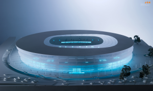
Thanks to façade treatment stadium appears to be light and transparent despite its massive size. The façade mesh protects the usable yet open space of the promenades from weather conditions such as rain and wind. Internal LED lighting system was introduced allowing the building to project light through the façade’s mesh from inside. Overall impression of the “glowing” building is similar to that of the Chinese lantern. Thanks to the LED technology colour and pattern of the lighting can be easily changed thus the building’s character can be visually adjusted to the planned event (such as EURO 2012, league and national tournaments, music shows or other mass events) and can generate particular feel to it following the current need.

Olympic Shooting Range – Temporary

With the London Summer Olympic Games rapidly approaching, there has been much talk about either the games are in fact economically good for a city. At its best, hosting an Olympics can help revitalize a city, and at its worst, playing host can leave the host-country drowning in debt.
There are a lot of reasons for this, but one is simply the cost of building new venues, all with a price tag to match their state-of-the-art design. When the athletes and fans pack up and go, the new stadiums and event-specific venues–for example, the Athens Olympics had a venue just for taekwondo– are often left empty, and unused far before the bill is settled.

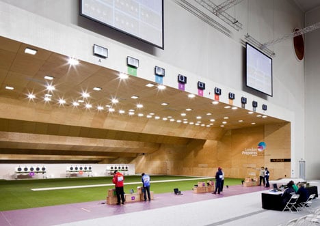
In London, there has been a little of everything, from big name high-priced venues to littler, temporary structures. But how do you make a temporary building that still has an architectural impact? Perhaps in an effort to answer this question, London and Berlin-based Magma architecture came up with a design for the Olympic Shooting Gallery that could be dismantled, but that you won’t soon forget.
Olympic Shooting Venue by Magma Architecture

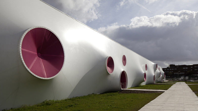
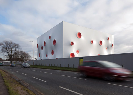
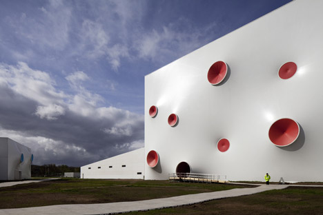
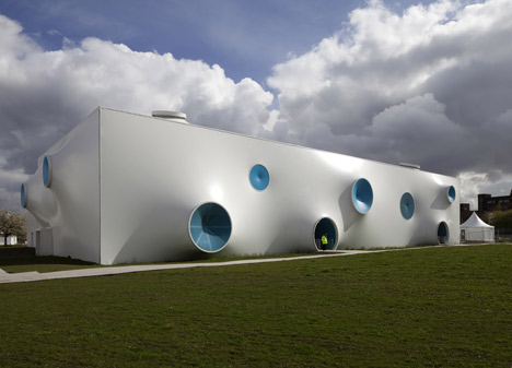
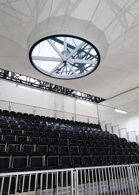
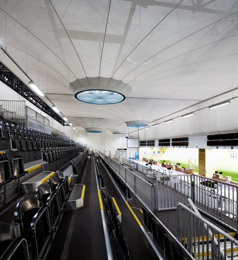
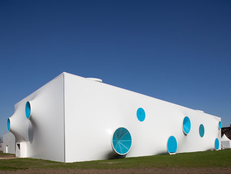
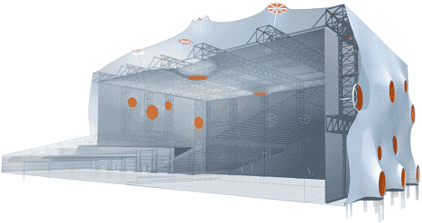
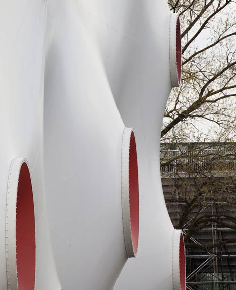
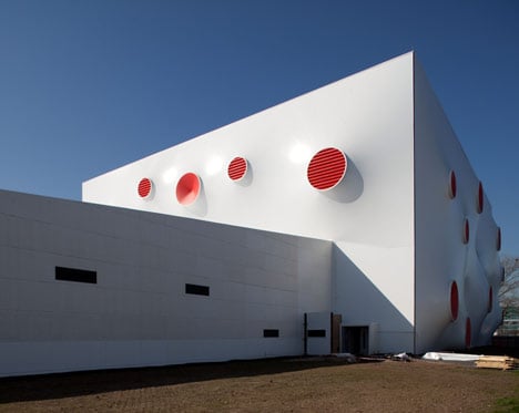
The shooting galleries for the London 2012 Olympic games are covered in spots that look the suckers of an octopus’ tentacles.
Olympic Shooting Venue by Magma Architecture
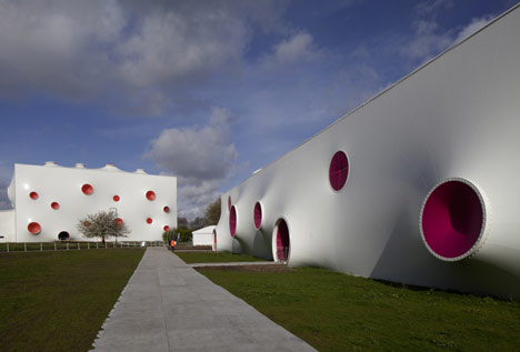
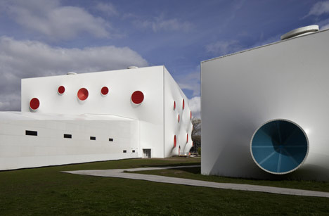
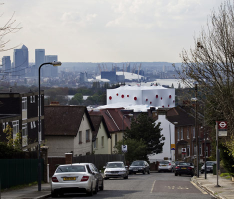
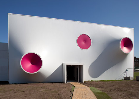
Designed by Magma Architecture of London and Berlin, the Olympic Shooting Venue comprises three PVC tents that have been erected at London’s historic Royal Artillery Barracks in Woolwich.
Olympic Shooting Venue by Magma Architecture
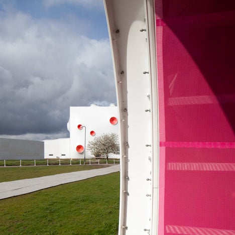
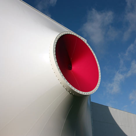
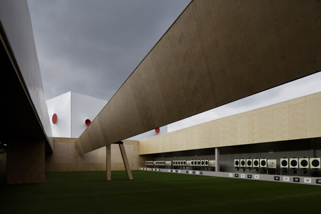
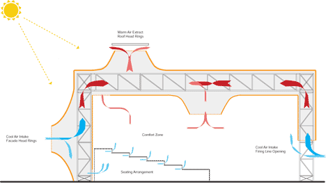
The extruded red, blue and pink circles draw ventilation inside each of the venues and also create tension nodes for the steel structure beneath the white skin.
Olympic Shooting Venue by Magma Architecture
Some natural light permeates this PVC membrane, while entrances are contained inside all the spots that meet the ground.
Olympic Shooting Venue by Magma Architecture
As the structures are only temporary, they will be dismantled immediately after the Olympics and reassembled in Glasgow for the 2014 Commonwealth Games.
Olympic Shooting Venue by Magma Architecture
Photography is by J.L. Diehl unless otherwise stated.
The text below is from Magma Architecture:

?London Shooting Venue
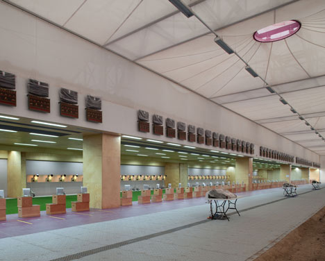
The London Shooting Venue will accommodate the events in 10, 25 and 50 m Sport Shooting at the 2012 Olympic and Paralympic Games in the southeast London district of Woolwich.
Olympic Shooting Venue by Magma Architecture
The first Gold Medal of the London Olympic Games will be awarded at the venue for Women’s 10 m Air Pistol on the 28th July 2012. After the event the three temporary and mobile buildings will be dismantled and rebuilt in Glasgow for the 2014 Commonwealth Games.
Olympic Shooting Venue by Magma Architecture
Shooting is a sport in which the results and progress of the competition are hardly visible to the eye of the spectator.
Olympic Shooting Venue by Magma Architecture
The design of the shooting venue was driven by the desire to evoke an experience of flow and precision inherent in the shooting sport through the dynamically curving space.
Olympic Shooting Venue by Magma Architecture
All three ranges were configured in a crisp, white double curved membrane façade studded with vibrantly colored openings.
Olympic Shooting Venue by Magma Architecture
As well as animating the façade these dots operate as tensioning nodes.
Olympic Shooting Venue by Magma Architecture
The 18.000 m2 of phthalate-free pvc membrane functions best in this stretched format as it prevents the façade from flapping in the windt.
Olympic Shooting Venue by Magma Architecture
Photograph by Steve Bates
The openings also act as ventilation intake and doorways at ground level.
Olympic Shooting Venue by Magma Architecture
Photograph by Steve Bates
The fresh and light appearance of the buildings enhances the festive and celebrative character of the Olympic event.
Olympic Shooting Venue by Magma Architecture
With the buildings being dismantled after the event an additional aim was to create a remarkable design which will be remembered by visitors and the local community thereby leaving a mental imprint the Olympic of shooting sport competition in Woolwich.
Olympic Shooting Venue by Magma Architecture
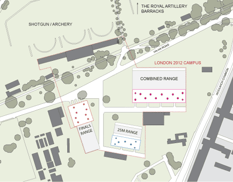
The shooting venue is not situated in the Olympic Park, but has its own location in Woolwich on the grounds of the historic Royal Artillery Barracks.
Olympic Shooting Venue by Magma Architecture
Photograph by Steve Bates
It is estimated that more than 104.000 spectators will watch the competitions.
Olympic Shooting Venue by Magma Architecture
Photograph by Steve Bates
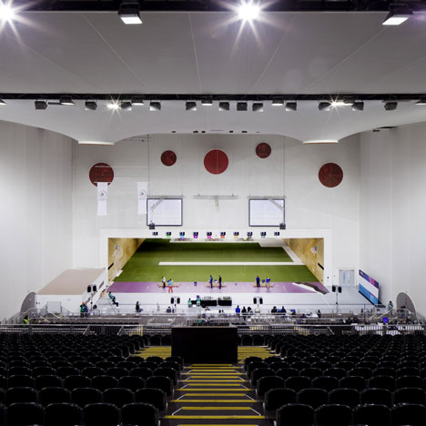
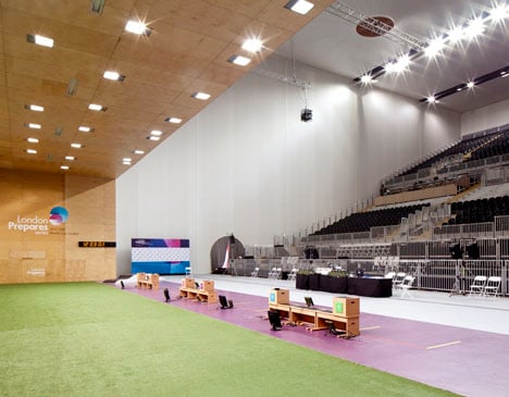
The three buildings comprise 3.800 seats divided between two partially enclosed ranges for the 25 and 10/50 m qualifying rounds and a fully enclosed finals range. Together they form a campus on the green field.
Olympic Shooting Venue by Magma Architecture
Photograph by Steve Bates
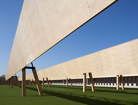
Their up to 107 m long facades refer to the structured length of the Royal Artillery Barracks building, but have their own contemporary architectural expression.
Olympic Shooting Venue by Magma Architecture
Guided by the high requirements from the client, the Olympic Delivery Authority, sustainability was a key factor in shaping the design. All materials will be reused or recycled.
Olympic Shooting Venue by Magma Architecture
All three of the venues are fully mobile, every joint has been designed so it can be reassembled; and no composite materials or adhesives were used. In addition, the semitransparent facades on two of the three ranges reduce the need for artificial lighting and the ventilation is fully natural.
Olympic Shooting Venue by Magma Architecture
The tensioning detail was achieved through an efficient configuration of modular steel components commonly used in temporary buildings market. The double-curvature geometry is a result of the optimal use of the membrane material, which magma architecture has been experimenting with for a number of years, amongst others in the award winning head in I im kopf exhibition at the Berlinische Galerie in Germany.
Olympic Shooting Venue by Magma Architecture
Magma archtitecture was founded in 2003 by the architect Martin Ostermann and the exhibition designer Lena Kleinheinz. Central to our work is the use of complex geometric modeling as a way of creating a more spatially dynamic vocabulary. This is essential to better articulate and reflect the heterogenieity of our cities and global culture.
Olympic Shooting Venue by Magma Architecture
We seek to be part of a new paradigm within architecture – one that is expressionistic, rooted in non-linear form-making and facilitated by new materiality and cutting edge technologies.

Tensile – The New Design Vocabulary in Structure and Architecture

Tensile The New Design Vocabulary in Structure and Architecture

Tensile has its roots in Ancient History

The history of tensile structures and tent-type housing, is as old as mankind itself. Leaves, barks leather and felt, existed much before fabrics.

The Ancient Egyptians were probably the first civilization to use pieces of fabric for shade. They also found sails useful for harnessing the power of the wind to travel in sailing boats from 3,500 BC.

Equipped with a Master’s in Membrane Structure, from Germany, Bhavini Mistry Jotani, M Archineer, engineers all design projects under the uniquely named Ahmedabad based Freitagmann, which specializes in designing, engineering and execution of light-weight structures and Innovative structures. Her views on the history of tensile forms is equally unique, “When I think of tensile, the Bedouin tents and the old Indian/arab markets with fabric roofs comes into my mind. But that is very personal and contextual,” and adds “In today’s times when one says tensile architecture, there is a whole new architectural language that springs up. Right from the big stadia and airport roof canopies to large span public spaces and mall-atriums.”

Tensile The New Design Vocabulary in Structure and Architecture
McCoy DDA Games Village New Delhi CWG2010

Today, tensile architecture repre- sents, ease of use, light, elegant, versatile and sturdy fabric, that builders and architects endorse.

What comes to your mind, instantly, when you hear or read the word ‘Tensile Architecture’? We asked some profes- sionals using tensile fabrics with excellent, long-term results.

Richard Mcdonald, President, Taiyo Membrane, India Operations —

“Simplicity in geometric form but complex in design”!

Tensile The New Design Vocabulary in Structure and Architecture

Shehzad Irani, M Archineer, SCHAFBOCK– “Free flowing forms, fabric, lightweight structures, open spaces, warm natural light.”

Simran Dodeja, Senior Marketing Manager, McCoy Architectural Systems “Light weight structures, versatile, dynamic, free flowing forms, archite- cture in motion.”

Tensile membrane applications

Tensile The New Design Vocabulary in Structure and Architecture

Tensile The New Design Vocabulary in Structure and Architecture

While all agree that atrium structures, large canopies at airports, amphi- theatres, stadia, car parks, bus drop-offs, garden structures, cafeteria, food courts and gazebos, mall coverings, would benefit tremendously from the high translucency and properties of the membrane structure. Faraz Aqil, Director, Mehler Texnologies, adds a note of caution, “For best and long-term results, fabric selection plays an important role and the end users must be briefed on maintenance and cleaning of these structures.”

The advantages to the builder, to the architect, and to the end users, of tensile architecture, in place of the erstwhile used methods and fabrics

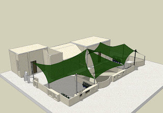
Reveals Shehzad Irani, “Using a tensile membrane roofing structure, reduces the overall loads on an existing structure, if designed properly. It gives a very good light quality, thereby reducing the overall illumination expenses of a space; the membrane roof itself is very flexible and hence is able to deflect considerably and hence resists earthquake loads. It also has a very small cross-sectional area, and hence cools down very quickly. Therefore in temperate climates, it doesn’t trap the heat in its mass. It is quite eco-friendly since the fabric is easily recyclable and the rest of the structure is steel, which can also be re-used. The manufacture of any of the components does not entail any toxic methodologies. They are very quick to install and demolish, since they are mostly pre-fabricated structures. They have a very low mass and hence can be even designed to retract/collapse easily”.
Tensile The New Design Vocabulary in Structure and Architecture

Ravi Mehta, who has shared his views on the advantages of tensile, on many occasions, gives a comprehensive list, that is technically precise and convincing. “The major advantage of using Textile roofing solutions is that, it allows natural light of very good quality, creating a very natural ambience, as it eliminates the need for artificial lighting, during daytime. Other materials like Glass or Polycarbonate, which also allow natural light, have the disadvantage of intense heat-gain, which necessitates high air-conditioning loads. Compa- ratively, Textile Architecture has lower heat gain and especially with certain solutions like Low E-membranes and double membranes, the requirement of air-conditioning can be reduced substantially. Being translucent, and not transparent like Glass, membrane diffuses the light through its entire surface and therefore at night, the entire roof comes alive and becomes a landmark with the illumination inside the roof.

Tensile The New Design Vocabulary in Structure and Architecture
Manipal Food Court Polyklad

Fabric being flexible, allows the architect to create striking forms and signature structures, extremely difficult with other rigid materials. If required, fabric structures can be designed to be modular and dismantlable. Being light, and flexible, they can also be easily stored and transported. A wide range of colors are available in certain types of fabric with customized options.”

Tensile The New Design Vocabulary in Structure and Architecture

Bhavini Mistry Jodani gives a comparative analysis, “The best advantage to the builders, is the coverage area, versus the cost per square meter area, when one compares tensile structures with regular concrete structures, or even run of the mill roofing solutions. The aesthetics of the tensile membrane structure, is always an architect’s delight, the light quality and the form of tensile, is like poetry.

Tensiles completely change the space quality. The volume of space that one gets in doing a tensile roof helps in decreasing the room temperature, especially in a tropical climate like ours. On the technical side, the cross section of tensile fabric is less and also fabric color is mostly white. A great percentage of sunlight is reflected back, while the thickness of membrane is so less compared to the concrete structure that it cools down equally faster. The amount of radiation from the membrane is lesser than a concrete structure.”

Simran Dodeja gives it a new dimension, “Tensile membrane structures offer versatility of form, giving the designer the ability to think on ‘out of the box’ solutions, virtually impossible with other materials. The pre-fabricated nature of these structures reduces construction time, allowing other on-site jobs to be completed simultaneously. Membrane Structures offer both roof and cladding, in one structural element.”

Faraz Aqil says that, besides being light, tensile fabrics are easy to install and maintain. They can be used to cover large areas with clear spans, they can take any form, shape or size; natural light helps in providing better surroundings and better ambiance.

Richard Mac Donald, wraps it up real crisp, “Pleasing to the eye, aesthetics, spanning large distances with minimal steelwork.”

Construction materials used towards ‘Green building objectives’ and Reduced ‘Carbon footprint’

Tensile The New Design Vocabulary in Structure and Architecture
Tensile Structures for reduced carbon footprint

“Construction activities consume voraciously – energy, and other materials, which have very high impacts on our carbon footprint. If we could use lesser materials by using more of our brains, it would go a long way in helping the environment; eventually leaving more for future generations to build with, especially in this time and age, when we have a lot of cutting edge software and tools, that can enable us to use less and lesser material for our buildings. Materials such as ‘Technical textiles’ can help in changing this attitude of want on use of materials, and move towards judicious use,” explains Shehzad Irani.

The strongest boost for the construction and building materials industry, is the bar rising initiated by the national planning departments that focus on ‘green’ building. The green building materials market is growing exponentially, with the residential market being a major driver. In addition to the residential market, efforts are been taken to use construction products that are manufactured, from renewable resources. Added to this, is the use of tensile fabrics, that have distinctive advantages, in promoting the ‘Green Building’ concept, in India’s construction arena.

“Tensile membrane Architecture is eco-friendly and is 100% recyclable. Even structures that support the membrane use steel, that is 100% recyclable, making this form of architecture perfect to achieve Green Building Solutions. Membrane structures allow diffused light and also help reduce heat load and can be extensively used as an alternative, to glass skylights, making these structures truly energy efficient” adds, Simran of McCoy.

Faraz Aqil boasts of Mehler’s eco-friendly fabrics, “We are committed to using greener technology and almost all our products are 100% recyclable. Mehler eco-care & Vinyl 2010 contribute to preserve the environment.”

Tensile The New Design Vocabulary in Structure and Architecture
Taiyo Membrane Expo 88 from the Brisbane River

Today’s software tools for today’s tensile architecture

“Nowadays a lot of non-linear, FDM based software have come into market like Forten4000, EASY, NDN. New software technology is being developed,, based on dynamic relaxation method, called Rhino membrane,” shares Bhavini Mistry Jotani.

Tensile The New Design Vocabulary in Structure and Architecture

Shehzad Irani, elaborates on the software packages that drive tensile architecture, “You require a FEA (finite element analysis) package that can do linear and non-linear structural analysis, a Force Density method based form-finder, to find the form for the structure, a patterning software, that can handle complex flattening of geodesic curvatures. ixForten 4000, is a very comprehensive and cost-effective tool. In addition, you need a Nurbs-modeling software that can handle 3Ds and easily prepare fabrication drawings. Vector- works, Rhino 4, Autocad, Revit, are all versatile software aids.

Challenges in using tensile fabrics

Tensile The New Design Vocabulary in Structure and Architecture Tensile The New Design Vocabulary in Structure and Architecture
Mehler texnnologies In Orbit Mall

In India, it is more the mental block of builders, consumers, architects and designers, who are not exposed to the changing trends, and remain soaked in age-old materials that are cheap and culture – friendly, that instill apprehe- nsions in their minds, to accept and adopt new membranes like tensile; resulting in the limited use of tensile fabrics in construction, besides the cost of these light fabrics.

Laments Bhavini, “The biggest challenge faced right now, is the base price of the material, since the fabric is not manufactured in India. We end up paying 30-40% more price compared to the European market, where most of the fabrics are also manufactured. Chinese fabrics are available in the market, but the quality is not reliable. More awareness needs to be created for the use of right technology and the benefits of tensile structures. One of the biggest challenge, in India, is to remove the blocks from people’s minds, that fabric does not mean temporary. Because of the flexibility of the material and the age old use of fabric (eg. Shamianas, temporary extension of shops during monsoons and summer) in our country, people have this notion, that the life of the structure is not long. On the contrary, with the strength the material possesses and the quality of the fabric that is available, the life of the structure can be from 15 to 35 years which more or less can be considered a permanent structure.”

Stressing on the need of the hour, Simran of McCoy says, “The biggest challenge that Tensile Fabric faces in India, is to create awareness about membrane architecture, which still remains to be explored by many designers and builders in the Country.”

Shehzad feels the lack of compe- tency in handling geometric precisions, in tensile architecture, “Fabric structure costs much more because of the rich specifications that have to be offered with it. They are extremely complex to design and engineer, since the behavior of the structure, geometry as well as the material is non-linear. Their installation, production requires, trained and skilled personnel, which is scarce in India.”

Faraz Aqil too lays emphasis on quality, “This is a cost effective solution, and not rocket science, but it is important to execute projects efficiently and fabricators should not compromise on the basic technical aspects of execution, in order to save costs.”

Richard Mac Donald is completely aware of the situation and challenges, and hence, is brutally honest in his views, as to how the myths of the practising architects, can ruin the image of the membrane industry, “Getting architects and developers to accept the cost of using membrane. They believe a thin material is not necessarily durable and long lasting. Roofing companies, new to the industry, not understanding the complexities of tensile membrane structures and believing, it is easy to design and build and subsequently they produce a membrane structure, that is poorly designed, detailed and built; thus giving the membrane industry a bad name.”

Tensile The New Design Vocabulary in Structure and Architecture
Gera Germany Stadium

Tensile Membranes in India–Market Overview and Lead Players

Developing a Technical Guideline to Permanent Tensile Architecture 

The tensile structure business has grown considerably in the last 10 years, and is predicted to grow exponentially, in the coming years. Such structures are becoming bigger and more sophisticated, as contractors, engineers and architects develop more confidence in their designs and reinforce them with their execution. Although the field may have evolved and more clients are interested in using them, they are still considered to be special – a new technology. Tensile surface structures do not figure widely in the design vocabulary of architects, engineers, urban planners, building owners and national authorities, and till that happens, their application will continue to be restricted.

Market projections, for tensile fabrics, pre- and post-economic slowdown, may be difficult to express in figures, without an accurate and deep study, but conservative turnovers would be close to 50-75 crores, per year.

How do big names fare, in the wake of poor acceptance, by the industry, of this new age, light material?

Says Ravi Mehta of Sujan Impex, which represents FERRARI, in India, “Initially we faced a lot of skepticism from architects, who were not aware of this new concept. However, slowly, as the architects in India got more exposed to international trends, and with a lot of foreign architectural firms also taking up projects in India, the concept of textile architecture has gained wide acceptance. People are realizing that, tensile architecture can be permanent, with life spans over 25 years.”

Tensile The New Design Vocabulary in Structure and Architecture
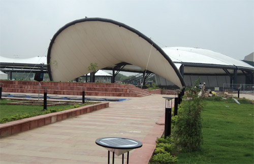
Hyderabad AIRPORT

Bhavini Mistry Jotani is optimistic about the market status, but is equally apprehensive of the cost and other issues. “India is an upcoming market for tensile structure. While European market is more or less saturated, and most of the international players are exploring the new asian markets, especially India and South East Asia. The tensile market in India, is around 15-20 years old. However, it is only for the last five years that it has been accepted in the Indian market. Many new players are coming into the market these days, but like any new technology or product in the market, some do justice to it by giving good solutions and by producing quality–tensile structure, while there are contractors who have half-baked knowledge and are invading the market, resulting in a disastrous end product, disappointing the end-user; creating a negative impact on the technology. I would say out of all the contractors and design-engineers in the field of tensile in India, only around 10-15% are qualified or have sufficient design-engineering knowledge of the technology and its application. Pre-recession saw fewer players, but the demand too was less. Post-recession has witnessed steep rise in the competition levels, almost 10 times, forcing everyone to quote competitive rates, and paradoxically, the base costs of fabric, steel and that of fabrication, have increased.”

Lead players of the Indian Tensile market

Taiyo Membranes, FERRARI, and Mehler Texnologies lead the TA march, towards the new-age architectural world in India. McCoy is the perfect partner in project execution.

Product features and applications

Faraz Aqil shares product features of his company, “Our Valmex FR Range, is one of the best PVC Coated Tensile memb- ranes available across the world.”

Salient features of Valmex FR includes: Both sides PVDF lacquered, 100% UV retardant, light weight and high strength, very easy cleaning and maintenance, resistance to microbial and fungal attack, translucent, thus enhancing power savings, flame retardant, 100% recyclable, a good example of environmentally safe and sustainable architecture, 10-15 years warranty and available in various width and sizes.

Tensile The New Design Vocabulary in Structure and Architecture
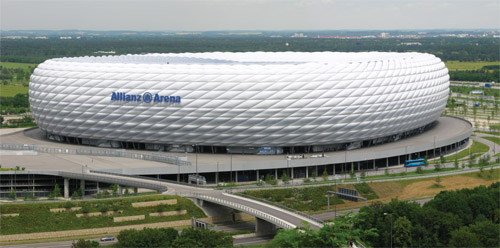
Munich Olympic Stadium

Ravi Mehta of Sujan Impex, says “FERRARI has a wide range of textiles for various exterior and interior applications such as, Permanent Roofing applications, Stretched Ceilings & Partitions, Solar Protection, Lightweight structures like tents, awnings & canopies.”

“FERRARI fabrics are made to suit all kinds of climatic conditions and are used in the coldest areas of Russia and North Europe, to the hottest desert areas of the Middle East. Tropical countries like Singapore and Malaysia use these fabrics widely” he adds.

Richard Mac Donald talks briefly his company’s excellence and product applications, “Taiyo is the oldest tensile membrane company in the world. It has over 50 years of experience in PTFE, PVC, ETFE, MDPE mesh and our company’s strength lies in design, detailing and ensuring high quality finishes. Our light-weight membranes are extremely durable for the harsh Indian environment. The most prominent membrane we sell is PTFE or Teflon coated fiberglass, which is extremely durable with a design life of over 50 years. PVC/PVDF is with a design life of 25 years, for the highest quality PVC fabric available in the market.”

Tensile The New Design Vocabulary in Structure and Architecture
Taiyo Port Elizebath Stadium

Simran shares information on the market status of McCoy, “McCoy Architectural Systems Pvt. Ltd. is known for its ability to design and execute the most Complex of Tensile Membrane Structures in India, with some very prestigious projects under its belt, like the D.Y. Patil Stadium Navi Mumbai, RK Khanna Tennis Stadium CWG 2010, DDA Games Village Swimming Pool Structures CWG 2010, and many more. The Company is constantly innovating in the field of Tensile Architecture and spreading awareness of Membrane Architecture through various methods.”

Shehzad confesses “Well very frankly, every fabricator would consider himself the leader, but some of the indigenous companies are–Western Outdoors, Shadeflex, Taiyo (not Indian), Construction Catalysers, McCoy Archite- ctural Systems, Skyshade technologies, Grorich, Polyklad, and Geodesic techniques.”

Bhavini Mistry Jotani feels “Tensile is the most apt material for our kind of climatic conditions. It’s just a matter of some time, before Tensiles would become an integral part of the Indian construction Industry.”

The future of Tensile Architecture, in India, may be uncertain, but one thing that remains undisputed is that, “Tensile is light, bright, tactile and versatile.”

Semester teaching at School of Architecture at Hemchandracharya North Gujarat University, Patan. 01 / 2011

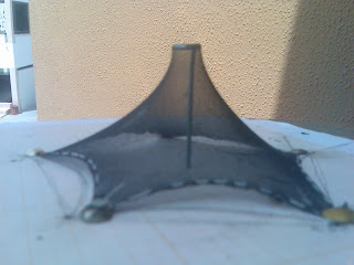
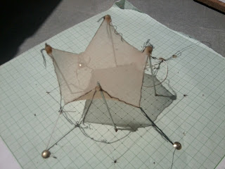
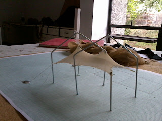
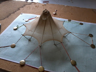
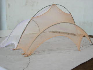
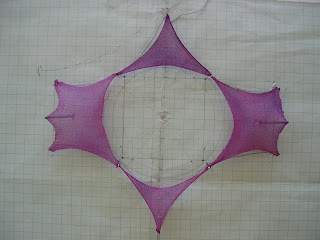
I had the good fortune of teaching a semester of lightweight structures at HNGU, Patan. The students made models and explored various aspects of tensile structures, grid structures, geodesic and space frame structures. some of their explorations are in images below. 
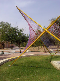
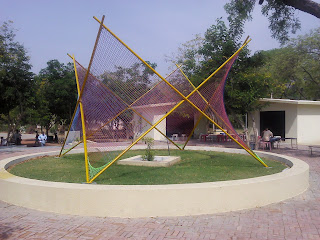
Sculpture with ropes

Attention to little details

vertical forms too..
The sculpture at the turn-about

Some other explorations

Two day IPSA Rajkot workshop 25 / 06 / 2010

A two day workshop was organised by IPSA, Rajkot for introducing students to concepts and applications of tensile structures. This workshop though short on time, was able to cover basic design aspects as the form-finding of such anti-clastic shapes and take them through basic systems of tensile structure. 

Poster for the workshop
Double cone structure
Bunching of fabric at the center. (it even has reinforcement sir!!!)

Three continuous cones.

KRVIA (Kamla Raheja Vidyanidhi, Mumbai) workshop with Ferrari

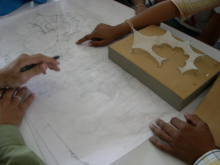
Teaching at KRVIA has been an excellent opportunity to interact with some very interested and inspired students. It was a three day workshop in which students learnt the basics, soap bubble modeling, stocking modelling, along with a healthy dose of tensile structures around the world and in India and how their detailing, engineering and conceptualization is done. There was a presentation by Ravi Mehta of Ferrari, who showed them the different types of fabrics and their applications around the world and in India. The Institute was also very interested in installing a prototype of a tensile structure and a special space was allocated near the canteen to install the same. Ferrari graciously supported the entire workshop. 
The students got a HANDS – ON experience at not only modeling designs using various software but also could extend these experiences to tangible solutions by putting up a structure of decent size to understand the forces that play in developing the form of the structure and the detailing involved about them. Some photographs of the workshop. 
Eager students await opening of the fabric

The “SMILEY” plate

And the other plate….

Students trying their hand at cut-outs.

Fixing details and laying out the cables in the fabric

Pretty maids – all in a row..

Fixing cables and the corner details

With a lil’ help from my friends…

And.. we are almost there…

Trampoline? Testing..? Just having fun… 

And some more fun… 

Quality issues – German Pavillion 15 / 11 / 2011

I had the unique opportunity to study up close the Indo German pavillions which are touring India – here are certain photographs of their production.. gives a great insight as to the working of such structures. 
Eye-lets on the edge

Fabrication errors

Fitting at the corner

How the designer thinks it should be…

Cargo Ratchets to tension the fabric

More Cargo ratchets

Facade with alternative panels

Flying mast with cables 
Termination of the cable

The fabric over-shooting the system

Fixing details at the edge

Balloon-ing effect due to tensioning of the fabric

Corner cut-out radius

Tensioning of the point.

Facade panels (mock-up)

Rajkot Workshop 26-02-2005

One of the first workshops that we took on tensile structures at IPSA rajkot. This one was to show them how tensile structures work with soap bubble models and using stockings. Students were guided in making shapes to describe such structures. The final project was to work out structures for a helipad and to cover the offices around the helipad. A three day workshop.

A New Begining….

For those who have been following this blog – and for those who haven’t been… firstly sorry, for the time since the last post. And doubly sorry, since in my anxiety to upload i deleted all my earlier post… Well it wouldn’t be my first experience at not backing up data and certainly not going to be my last experience at losing data… anyway, it is always new opportunity to start fresh – life gives us that each day…


Those who knew US, would know what i am talking of. It has been a glorious six years of working in Freitagmann from 2003 to 2010… But things have changed and have come to the level of bidding the heritage goodbye. 


Among the happy memories there were of course Apollo hospital and the ganesh umbrella which reminds us of our naivete.. and our incredible capacity at working with our hands for long periods of time. 


Then there was science city which we executed in 20 – 25 days, when we were just entering the world of computer aided tensile structures… and not really clear about all patterning and stuff…


There was IMS through which we made some great friends, and also along the way we have lost some dear ones…


There were immense number of times when we questioned where we stood and what we did and if we were moving in the right direction and if we were doing things that mattered… But principles drove us strong and long…


There were feeble attempts at discovery – and marvelous experiences at inventions. 


All this and more that shall be a part of our memory. Thank you all those who have been in these… Miss you we shall.


Aideu.

Apollo Green – Canopy

Figuring out the Ganesh canopy

Cutting patterns the old-fashioned way…

Thats the way to do the cnc plotting – completely not controlled

Ranpur. Creaseless and taut..

Made some new friends…

And lost some …

And some more…

Design Experimentation

And some funky stuff…
some good rendering attempts (for that time)

and some explorations

And the struggle between the virtual and tactile…

Events where we didn’t sleep for nights in a row…

Some quick work… that fetched us results…

On the job and look out for problems..

Somethings that didn’t quite fit..

Sketch – before iPad and SketchUp and Samsung galaxy Tab

Even aesthetic inputs… the first Vibrant Gujarat at Science City..

And thats what happens to fabrics that elongate…