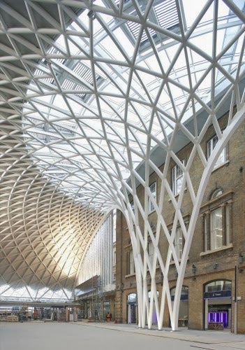
While Mumbai’s Chatrapati Shivaji Station and Mumbai Central remains the depressing mess it has always been for half a century, with the minimal eye-wash we call “development” such as the Hafez Contractor’s attempt at grilling sweaty mumbai travellers on a spit under a leaky polycarbonate concept that doesn’t follow the gothic nor Pompidou, Londoners now travel with comparative ease beneath the white-painted steel tubes rising in a half-dome at King’s Cross Station.
The new roof is a contemporary engineering spectacle, yet very much in the spirit of London’s great Victorian iron-and- glass rail extravaganzas. It just goes to show that the railway (though much of it already shed its mass by getting sold to the public) is still very much vibrant in its responses to travellers needs and comfort in transport is still a very big public issue. It is the inspired solution to expanding King’s Cross when a tangle of crisscrossing Tube lines seemed to leave no place to grow.
As mumbai keeps sinking hundreds of crores into middlemen and supposedly widening, refurbishment and improvement of some corridors and making new entrances — it barely is a Band-Aid for an area mobbed by over million passengers every day. Monsoons make it worse, and the summers destroy the commuter’s morale.
It’s worth having a look at how the elegant $880 million Western Concourse of the 1852 King’s Cross depot addresses so many challenges for just its 150,000 daily passengers. It is also worthy to look at the means employed, the elegance, the sincerity of addressal of all problems collectively and sustainably.
Architect John McAslan & Partners, working with the engineering firm Arup, faced two problems. To simplify connections between the train and six Tube lines, the new Western Concourse had to be built on the west side of the old station. That meant placing it above a new London Underground Ltd. ticketing concourse, which had been built without room to place supports for the latest addition.
Elegance
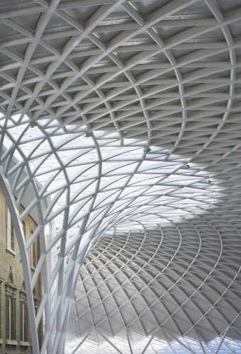
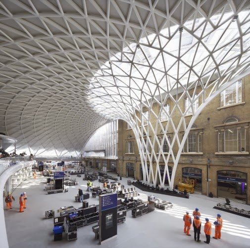
McAslan and Arup found an elegant solution for the support problem, placing 17 massive piers outside the box of the London Underground concourse. Atop them they set the semicircle of crisscrossing steel tubes that rises 66 feet in a tall funnel shape with a 230-foot radius.
The diagonal-grid construction looks lightweight and seems to settle gently upon the piers. It triples passenger accommodation, according to information provided by the project. Under the spreading roof, McAslan tucked a mezzanine where cafes offer nice views of the pulsing flow of passengers below.
The location of the new concourse, well away from the frontage on busy Euston Road, would strike us as odd until you understand that it puts passengers a short walk to connections at the adjacent St. Pancras station, rather than unload them all out into a mess.
Simultaneously, Foster & Partners built an elegantly functional light- filled shed behind St. Pancras in 2007, to cover platforms extended to accommodate Eurotunnel trains, regional-rail lines and long-distance trains operated by Network Rail.
Method
The transformation of King’s Cross Station for Network Rail involves three very different styles of architecture:
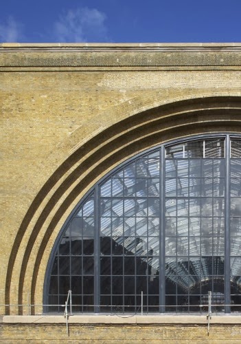
Rre-use, restoration and new build. The train shed and range buildings have been adapted and re-used, the station’s previously obscured Grade I listed façade was precisely restored, and a new, highly expressive Western Concourse has been designed as a centrepiece and the ‘beating heart’ of the project. When the station opened to the public on 19 March 2012, King’s Cross became a new, iconic architectural gateway to the city, ready for the 2012 London Olympics. The design re-orientates the station to the west, creating significant operational improvements and reveals the main south façade of Lewis Cubitt’s original 1852 station.
Although the Western Concourse is probably the most visually striking change to the station, JMP’s work on the project also involved a series of layered interventions and restorations including the restoration of the Eastern Range building and the revitalisation of the Main Train Shed, Suburban Train Shed and Western Range buildings.
WESTERN CONCOURSE
The centrepiece of the £500m redevelopment is the new vaulted, semi-circular concourse to the west of the existing station. The concourse rises some 20m and spans the full 150m-length of the existing Grade I Listed Western Range, creating a new entrance to the station through the south end of the structure and at mezzanine level to the northern end of the Western Concourse, thereby at
7,500sqm the concourse has become Europe’s largest single-span station structure, comprising of 16 steel tree form columns that radiate from an expressive, tapered central funnel. The graceful circularity of the concourse echoes the form of the neighbouring Great Northern Hotel, with the ground floor of the hotel providing access to the concourse.
The Western Concourse sits adjacent to the façade of the Western Range, clearly revealing the restored brickwork and masonry of the original station. From this dramatic interior space, passengers access the platforms either through the ground level gate-lines in the Ticket Hall via the Western Range building, or by using the mezzanine level gate-line, which leads onto the new cross–platform footbridge.
Located above the new London Underground northern ticketing hall, and with retail elements at mezzanine level, the concourse will transform passenger facilities, whilst also enhancing links to the London Underground, and bus, taxi and train connections at St Pancras.
The concourse is set to become an architectural gateway to the King’s Cross Central mixed-use developments, a key approach to the eastern entrance of St Pancras International. It will also act as an extension to King’s Cross Square, a new plaza that will be formed between the station’s southern façade and Euston Road.
MAIN TRAIN SHED
The station’s Main Train Shed is 250m long, 22m high and 65m wide, spanning eight platforms. The restoration includes revealing the bold architecture of the original south façade, re-glazing the north and south gables and refurbishing platforms The two barrel-vaulted roofs are refurbished and lined with energy-saving photo-voltaic arrays along the linear roof lanterns, while a new glass footbridge designed by JMP extends across the Main Train Shed, replacing the old mid-shed Handyside bridge and giving access to every platform as well as the mezzanine level of the concourse.
JMP’s design integrates the main and suburban train sheds for the first time, creating a completely coherent ground-plan for passenger movements into and through the station. Improvements to the Suburban Train Shed located to the north of the Western Concourse and Western Range buildings have enhanced the operation of its three platforms (the busiest in the station during peak-hours).
Read more about the plan and the vision in this document.


